 +86 138 8989 6699


RKS fluid was founded in 1997. We are a production workshop for both foundry and machining, research & development center, and quality inspection cent...

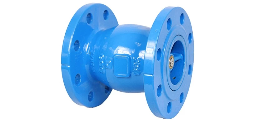
Swing check valve is mounted with a disc that swings on a hinge or shaft. The disc swings off the seat to allow forward flow and when the flow is stop...

Features: Fully bore globe pattern design, lowest head loss while fully open Keep stable working condition even the flow rate close to zero High sens...

Ⅰ Business area: fluid control products, technology and environmental protection products. Ⅱ Advanced CNC machining centers, professional process ce...

RKS fluid was founded in 1997. We are a production workshop for both foundry and machining, research & development center, and quality inspection cent...

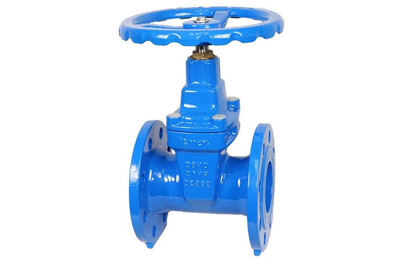
Series: SASQUATCH series soft seal gate valve Port size: DN50 - DN900 (NPS2-NPS36) Pressure rating: PN10, PN16 Temperature: 0℃~80℃ Connection: Flange Certificate: CE ,WRAS,API,OHSAS18001:2007,ISO9001:2015


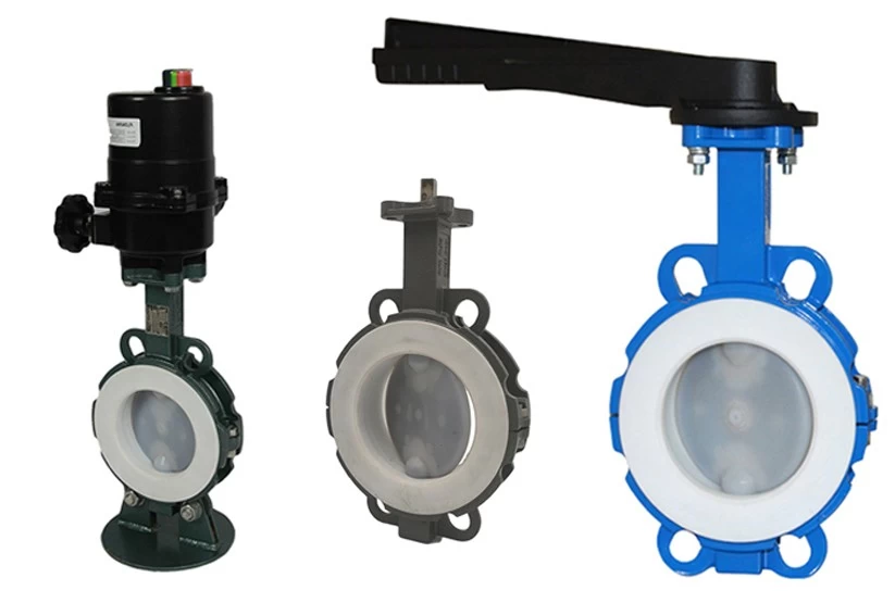
Butterfly valves have been around for a long time, and are used for a variety of applications. They made their first appearance during the 1930s, and have been utilized by several industries ever since. Often made out of cast iron, butterfly valve's name is based from the functionality of its disc.

The wafer butterfly valve is one of the most common types of valves in industrial pipelines. The structure of wafer butterfly valve itself is relatively small. It is only necessary to put the butterfly valve in the middle of the flange at both ends of the pipe, and use the stud bolt to pass through the pipe flange and the pair.
 Work?")

Valves are the most common equipment in chemical companies. It seems easy to install valves, but if they are not implemented in accordance with the re...

The manual valve is a valve operated by the handle and the hand wheel, and is a commonly used valve on the equipment pipeline.

DIN standard now uses EN standard structure length
EN 558-1 PN flange connection valve construction length (instead of DIN 3202), EN 558-2 CLASS flange connection valve construction length (instead of BS2080), EN 12982 butt weld end valve construction length (instead of DIN 3202), DIN standard The length of the structure including the length of the API valve is basically the same as the length of the GB...

The butterfly valve disc is a key component of the butterfly valve, which acts on closing and opening and closing. Butterfly valve seat and butterfly ...

Resilient-seated gate valve with bolted cover connection; made of ductile iron materials and with epoxy coating, designed as both clockwise and anti-c...
What is Kieselguhr Filter? What's the working principle of Kieselguhr Filter? The kieselguhr filter (Candle filter / Cake Filter) which we for customized for fluorine chemical plant six more lithium fluoride phosphate phosphorus process have been installed and working for two years

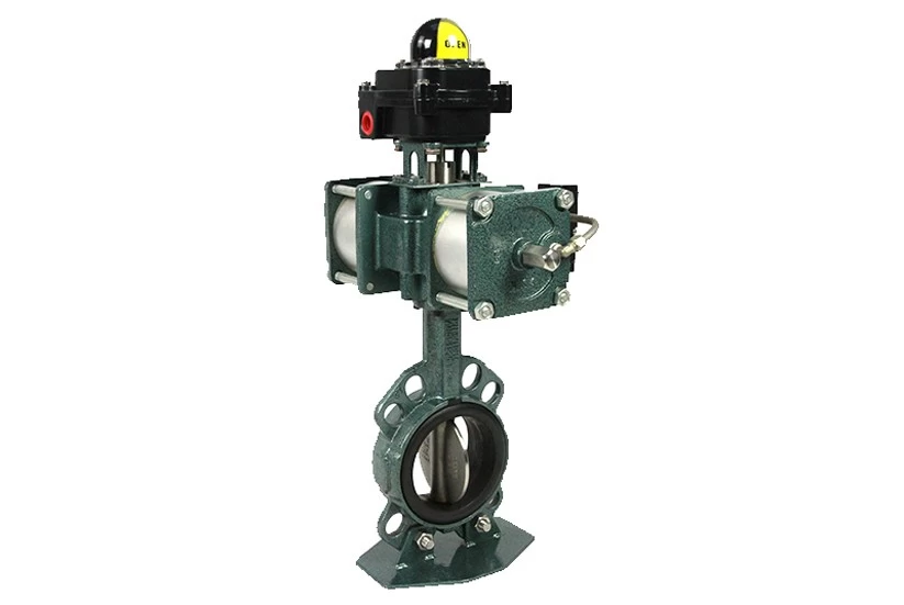
MINOTAUR series replaceable seat high performance butterfly valve
Basic terminology
1. Strength performance
The strength properties of a valve are the ability of the valve to withstand the pressure of the medium. Valves are mechanical products that withstand internal pressure and must therefore have sufficient strength and rigidity to ensure long-term use without cracking or deformation.
2. Sealing performance
The sealing performance of the valve refers to the ability of the sealing parts of the valve to prevent the leakage of the medium. It is the most important technical performance index of the valve.
There are three sealing parts of the valve: the contact between the sealing surface of the opening and closing parts and the valve seat; the joint of the packing with the valve stem and the stuffing box; the connection between the valve body and the valve cover. The leak in the former place is called endoleak, which is commonly referred to as the lack of tightness, which will affect the ability of the valve to cut off the medium.
For shut-off valves, internal leakage is not allowed. The latter two leaks are called external leaks, ie the medium leaks from the valve to the outside of the valve. External leakage can cause material loss, pollute the environment, and cause accidents in severe cases.
For flammable, explosive, toxic or radioactive media, external leakage is not allowed, so the valve must have a reliable sealing performance.
3. Flowing media
When the medium flows through the valve, pressure loss (both pressure difference before and after the valve) is generated, that is, the valve has a certain resistance to the flow of the medium, and the medium consumes a certain amount of energy in order to overcome the resistance of the valve.
In terms of energy conservation, when designing and manufacturing valves, it is necessary to reduce the resistance of the valve to the flowing medium as much as possible.
4. Opening and closing force and opening and closing torque
The opening and closing force and the opening and closing torque refer to the force or moment that must be applied when the valve is opened or closed.
When closing the valve, it is necessary to form a certain sealing specific pressure between the opening and closing parts and the sealing surface of the bearing seat, and at the same time overcome the between the valve stem and the packing, between the thread of the valve stem and the nut, and at the end of the valve stem and The friction of other friction parts must be applied with a certain closing force and closing torque. During the opening and closing process, the required opening and closing force and opening and closing torque are changed. The maximum value is the final moment or opening of the closing. The initial moment. When designing and manufacturing valves, it is desirable to reduce their closing force and closing torque.
5. Opening and closing speed
The opening and closing speed is expressed by the time required for the valve to complete an opening or closing action. Generally, there is no strict requirement for the opening and closing speed of the valve, but some working conditions have special requirements for the opening and closing speed. If some requirements are quickly opened or closed, in case of accidents, some requirements are required to be slowly closed to prevent water hammer, etc. This should be considered when selecting the valve type.
6. Motion sensitivity and reliability
This refers to the sensitivity of the valve to the corresponding changes in the media parameters. For valves with regulating functions such as throttle valves, pressure reducing valves, regulating valves, etc., as well as valves with special functions such as safety valves and traps, their functional sensitivity and reliability are important technical performance indicators.
7. The service life
It indicates the durability of the valve, is an important performance indicator of the valve, and has great economic significance. Usually indicated by the number of opening and closing times that can guarantee the sealing requirements, it can also be expressed by the use time.
8. Type (type)
Classification of valves by use or main structural features
9. Model (model)
Numbering the valve by type, transmission, connection type, structural characteristics, seat sealing surface material and nominal pressure.
10. Connection dimensions (connection dimensions)
Valve and pipe joint size
11.The main dimensions (general dimensions)
Valve opening and closing height, handwheel diameter and connection size.
12. The type of connection (type of connection)
The various ways in which the valve is connected to the pipe or machine (eg flange connection / threaded connection / welded connection, etc.).
13. Seal test (seal test)
Tests for the performance of the opening and closing parts and the valve body seal pair.
14. Back seal test (back seal test)
Test the sealing performance of the valve stem and bonnet seal pair.
15. Seal test pressure
The pressure specified by the valve during the seal test.
16. Suitable medium (suitable medium)
The medium to which the valve can be applied.
17. Applicable temperature (suitable temperature)
The temperature range of the medium to which the valve is applied.
18. Sealing face (sealing face)
The opening and closing member is in close contact with the valve seat (valve body), and serves as a sealing contact surface.
19. Opening and closing parts (disc)
A general term for a part used to cut off or regulate the flow of a medium, such as a gate in a gate valve, a valve flap in a throttle valve, and the like.
20. Packing (packing)
Load the stuffing box (or stuffing box) to prevent the media from leaking from the valve stem.
21. Packing seat (packing seat)
A part that supports the packing and keeps the packing sealed.
22. Packing gland (gland)
A part that is used to compress the packing to achieve a seal.
23. Bracket (yoke)
A part used to support the stem nut and transmission mechanism on the bonnet or valve body.
24. The dimension of connecting channel (dimension of connecting channel)
The structural dimensions of the joint between the opening and closing member and the valve stem assembly.
25. Flow area (flow area)
Refers to the minimum cross-sectional area between the inlet end of the valve and the sealing surface of the seat (but not the “curtain” area), used to calculate the
theoretical displacement without any resistance effects.
26. Flow diameter (flow diameter)
Corresponds to the diameter of the runner area.
27. Flow characteristics (flow characteristics)
In the steady flow state, when the inlet pressure and other parameters are constant, the outlet pressure of the pressure reducing valve is a function of the flow rate.
28. Flow characteristics derivation
In the steady flow state, when the parameters such as the inlet pressure are constant, the change in the outlet pressure caused by the change in the flow rate of the pressure reducing valve.
29. General valve (general valve)
Valves commonly used in pipelines in various industrial enterprises.
30. Automatic valve (Self-acting valve)
A valve that acts on its own depending on the capabilities of the medium (liquid, air, steam, etc.).
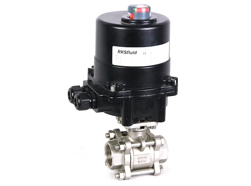
31. Actuated valve
Valves that are operated by manual, electric, hydraulic or pneumatic pressure.
32. Hammer blow handwheel
A handwheel structure that utilizes a striking force to relieve valve operating forces.
33. Worm gear transmission (wormgear actuator)
A device that opens or closes or adjusts a valve with a worm gear mechanism.
34. Pneumatic device (pneumatic actuator)
Use the pneumatic pressure to open or close or adjust the drive of the valve.
35. Hydraulic device (hydraulic actuator)
Use hydraulic pressure to open or close or adjust the valve's drive.
36. Hot condensate capacity (Hot condensate capacity)
The maximum amount of condensate that can be discharged from the trap in a given differential pressure and temperature
37. Steam loss (Steam loss)
The amount of fresh steam leaking out of the trap per unit time.
Valve definition term
1. Valve (valve)
The total number of mechanical products with movable mechanisms used to control the flow of media within the pipe.
2. Gate valve (slide valve)
The opening and closing member (gate) is driven by the valve stem, and the valve is lifted and moved along the valve seat (sealing surface).
3. Globe valve, stop valve
The open-close type (valve) is a valve that is driven by the valve stem and moves up and down along the axis of the valve seat (sealing surface).
4. Throttle valve
The passage cross-sectional area is changed by the opening and closing member (valve) to adjust the flow rate and pressure of the valve.
5. Ball valve
A valve that opens and closes (sphere) about a curve that is perpendicular to the passage.
6. Butterfly valve
Open-closed (butterfly) valve that rotates around a fixed axis.
7. Diaphragm valve
The open-close type (diaphragm) is a valve that is driven by the valve stem, moves up and down along the axis of the valve stem, and separates the action mechanism from the medium.
8. Plug valve (cock)
A valve that opens and closes (plug) about its axis.
9. Check valve, non-return valve
Open-closed (valve) A valve that automatically blocks the flow of media by means of medium force.
10. Safety valve, relief valve
Open-close type (valve) Automatically opens the discharge when the medium pressure in the pipeline or machine equipment exceeds the specified value; the valve that automatically closes when the pressure is lower than the specified value, and protects the pipeline or machine.
11. Pressure reducing valve
Through the throttling of the opening and closing member (valve), the pressure of the medium is lowered, and the valve pressure is automatically maintained within a certain range by the direct action of the pressure after the valve.
12. Steam trap
A valve that automatically discharges condensate and prevents it from leaking.
13. Draining Valves
Valves for the discharge of boilers, pressure vessels and other equipment.
14. Low pressure valve
Various valves with nominal pressure PN ≤ 1.6MPa.
15. Middle pressure valve
The nominal pressure is various valves with PN ≥ 2.0 ~ PN < 10.0 MPa.
16. High pressure valve
Various valves with nominal pressure PN ≥ 10.0 MPa.
17.Super high pressure valve
Various valves with nominal pressure PN ≥ 100.0 MPa.
18. High temperature valve
For various valves with media temperatures >450 °C.
19. Sub-zero valve
For a variety of valves with a medium temperature of -40 ° C ~ -100 ° C.
20. Cryogenic valve (cryogenic valve)
For various valves with media temperatures <-100 °C.
Valve structure terminology
1. Face-to-face dimension (face-to-centre dimension)
The distance between the inlet and outlet end faces of the valve; or the distance from the inlet end face to the outlet axis.
2. Straight-through valve structure length (through way type of valves Face to face dimensions)
At the end of the valve body passage, the distance between the two planes perpendicular to the axis of the valve axis.
3. Angle valve structure length(angle type of valves Face to face, end to end, center to face and center to end dimensions)
The distance between the plane perpendicular to the axis at one end of the valve body passage and the other terminal axis of the valve body.
4. Type of construction
The main features of various types of valves in terms of structure and geometry.
5. Through way type
The inlet and outlet axes are coincident or parallel to each other in the form of a valve body.
6. Angle type
The valve body forms that the inlet and outlet axes are perpendicular to each other.
7. Y-globe type, y-type, diaphragm type
The passage is in the form of a valve body in which the valve stem is positioned at an acute angle to the axis of the valve body passage.
8. Three way type
A valve body form with three passage directions.
9. T-pattern three way
The passage of the plug (or sphere) is of the general formula of "T" 。.
10. L-pattern three way
The passage of the plug (or sphere) is of the general formula of "L" 。.
11. Balance type
A structural form in which the axial force of the valve stem is balanced by the medium pressure.
12. Leverage type
The lever is used to drive the structure of the opening and closing member.
13. Normally open type (normally open type)
When there is no external force, the opening and closing member is automatically in the open position.
14. Normally closed type
When there is no external force, the opening and closing member is automatically in the closed position.
15. Steam jacket type
Various valves with steam heated jacket construction.
16. Bellows seal type
Various valves with bellows construction.
17. Full-opening valve
A valve with the same inner diameter of the flow passage in all parts of the valve and the same inner diameter of the nominal pipe.
18. Reduced-opening valve
A valve with a reduced diameter of the flow passage hole in the valve.
19. Reduced-bore valve
The diameter of the flow passage hole in the valve is reduced, and the valve opening of the valve closing member is a non-circular valve.
20. One-way valve (un-directional valve)
Designed as a valve that seals only one medium flow direction.
21. Bi-directional valve
Designed as a valve that seals both media flow directions.
22. Two-seat two-way valve (twin-seat, both seats bi-directional, valve)
The valve has two seal seats, and each valve seat has a valve that can seal both media flow directions.
23. One-way seat, two-way seat double seat valve (twin-seat, one seat un-directional and one seatsbi-directional, valve)
The valve with two sealing pairs, in the closed position, the two sealing pairs can be kept sealed at the same time, the valve body in the middle chamber (between the two
sealing pairs) has an interface for releasing the pressure of the medium. Represents the symbol DBB.
24. Back seat, back face
A sealing structure that prevents the medium from leaking from the stuffing box when the valve is fully open.
25. Pressure seal
It is used as a structure for automatic sealing of the joint between the valve body and the valve cover.
26. Dimension of valve stem head
The structural dimensions of the valve stem to the handwheel, handle or other mechanical attachment joint.
27. Dimension of valve stem end
The structural dimensions of the connection between the valve stem and the opening and closing member.
28. Dimension of connecting channel
The structural dimensions of the joint between the opening and closing member and the valve stem assembly.
29. Type of connection
The various ways in which the valve is connected to the pipe or machine (such as flanged connections, threaded connections, welded connections, etc.).
Valve component terminology
1. Body
Directly connected to a pipe (or machine) to form a part of the flow path of the medium.
2. Bonnet (bonnet, cover, cap, lid)
It is connected to the valve body and forms a main part of the pressure chamber with the valve body (or by other parts such as diaphragms).
3. Opening and closing parts (disc)
A general term for a part used to cut off or regulate the flow of a medium, such as a gate in a gate valve, a valve flap in a throttle valve, and the like.
4. Disc (disc)
Opening and closing parts in valves such as globe valves, throttle valves, and check valves.
5. Body seat (body seated ring, shoulder seated, bottom seat)
A part mounted on the valve body and forming a sealing pair with the opening and closing member.
6. Sealing face
The opening and closing member is in close contact with the valve seat (valve body), and serves as a sealing contact surface.
7. Stem (stem, apindle)
The opening and closing force is transmitted to the main part on the opening and closing member.
8. Stem nut (yoke bushing, yoke nut)
A part that forms a motion pair with the stem thread.
9. Stuffing letter
On the bonnet (or valve body), a packing is filled to prevent the medium from leaking from the valve stem.
10. Stuffing box
Fill the filler to prevent the media from leaking from the stem.
11. Packing gland (gland, gland flange, pne-piece glang)
A part that is used to compress the packing to achieve a seal.
12. Packing (packing, packing rings)
Load the stuffing box (or stuffing box) to prevent the material from leaking at the double valve stem of the media.
13. Packing seat, packing washer
A part that supports the packing and keeps the packing sealed.
14. Bracket (yoke)
A part used to support the stem nut and transmission mechanism on the bonnet or valve body.
15. Impact hand wheel(impact handwheel, hammer blow handwheelimpact handwheel, hammer blow handwheel)
A handwheel structure that utilizes a striking force to relieve valve operating forces.
Basic understanding of features
1. General requirements
1.1 Valve specifications and categories should meet the requirements of the piping design documents.
1.2 The model number of the valve should indicate the national standard numbering requirements. If it is an enterprise standard, the relevant description of the model should be indicated.
1.3 The working pressure of the valve requires ≥ the working pressure of the pipeline. Under the premise of not affecting the price, the working pressure of the valve should be greater than the actual working pressure of the pipeline; any side under the closed condition of the valve should be able to withstand 1.1 times the working pressure of the valve. The value does not leak; the valve body should be able to withstand twice the valve pressure requirements when the valve is open.
1.4 The valve manufacturing standard shall state the national standard number based on it. If it is an enterprise standard, the enterprise contract shall be attached to the procurement contract.
2. Valve quality
2.1 The body material should be made of ductile iron, and the actual physical and chemical test data of the grade and cast iron should be indicated.
2.2 Stem material, stainless steel valve stem (20Cr13), large diameter valve should also be stainless steel embedded valve stem.
2.3 Nut material, cast aluminum brass or cast aluminum bronze, and the hardness and strength are greater than the valve stem.
2.4 Stem bushing material, its hardness and strength should not be greater than the valve stem, and does not form electrochemical corrosion with the valve stem and valve body under water immersion conditions.
2.5 material of the sealing surface
1 valve types are different, sealing methods and material requirements are different;
2 ordinary wedge gate valve, the material, fixing method and grinding method of the copper ring should be explained;
3 soft sealing gate valve, physical and chemical testing data of valve plate lining material;
4 butterfly valve should indicate the material of the sealing surface on the valve body and the sealing surface material on the butterfly plate; their physical and chemical testing data, especially the hygienic requirements of rubber, anti-aging performance, wear resistance; usually use nitrile rubber and EPDM Rubber, etc., it is forbidden to use reclaimed rubber.
2.6 Valve shaft packing
1 Due to the valve in the pipe network, usually the opening and closing is not frequent, the filler is required to be inactive for several years, the filler is not aging, and the sealing effect is maintained for a long time;
2 The valve shaft packing should also be in good condition when it is subjected to frequent opening and closing;
3 In view of the above requirements, the valve shaft packing is intended to be replaced for a lifetime or not replaced for more than ten years;
4 If the packing needs to be replaced, the valve design should consider measures to replace it under water pressure.
3. Variable speed gearbox
3.1 The material of the box and the internal and external anti-corrosion requirements are consistent with the valve body principle.
3.2 The box should have sealing measures, and the box can be immersed under the condition of 3 meters water column after assembly.
3.3 The opening and closing limit device on the box, the adjusting nut should be inside the box or outside the box, but special tools are required to work.
3.4 The design of the transmission structure is reasonable. When opening and closing, the valve shaft can only be rotated, so that it does not move up and down, the transmission parts bite properly, and there is no separation and slip when the load is opened and closed.
3.5 The transmission gearbox and the valve shaft seal are not connected to a leak-free whole, otherwise there should be reliable anti-leakage measures.
3.6 There is no debris in the box, and the gear bite should be protected by grease.
4. Valve operating mechanism
4.1 The opening and closing direction of the valve should be closed clockwise.
4.2 Due to the valve in the pipe network, it is often manually opened and closed, the number of opening and closing rotations should not be too much, that is, the large diameter valve should also be within 200-600 rpm.
4.3 In order to facilitate a person's opening and closing operation, the maximum opening and closing torque should be 240N-m under the condition of pipeline pressure.
4.4 The valve opening and closing operation end shall be square and standardized in size and facing the ground so that people can operate directly from the ground. Valves with discs are not suitable for underground pipe networks.
4.5 Display panel of valve opening and closing degree
1 The scale line of the opening and closing degree of the valve shall be cast on the outer cover of the display panel after the gearbox cover or the direction of the change, and the surface shall be facing the ground, and the scale line shall be coated with phosphor to show eye-catching;
2 indicates that the material of the disc needle can be made of stainless steel when the management is good, otherwise it is painted steel, do not use aluminum skin;
3 indicates that the disc needle is conspicuous and firmly fixed. Once the opening and closing adjustment is accurate, it should be locked with rivets.
4.6 If the valve is buried deep and the operating mechanism and display panel are ≥1.5m away from the ground, the extension pole shall be provided and fixed firmly so that people can observe and operate from the ground. That is to say, the valve opening and closing operation in the pipe network is not suitable for downhole operation.
5. Valve performance testing
5.1 When a certain specification of a valve is manufactured in batches, an authoritative organization shall be entrusted to perform the following performance tests:
1 The opening and closing torque of the valve under the working pressure condition;
2 Under the condition of working pressure, it can ensure the tight closing and closing times of the valve;
3 The detection of the flow resistance coefficient of the valve under the condition of pipeline water delivery.
5.2 The valve shall be tested as follows before leaving the factory:
1 When the valve is open, the valve body should be subjected to internal pressure detection twice the valve pressure value;
2 Under the closed condition of the valve, the two sides respectively withstand 1.1 times the valve pressure value, no leakage; but the metal sealed butterfly valve, the leakage value is not greater than the relevant requirements.
6. Internal and external corrosion protection of the valve
6.1 Valve body (including variable speed transmission box) inside and outside, first shot blasting sand rust removal, and strive to electrostatically spray powdery non-toxic epoxy resin, the thickness of more than 0.3mm. When large-scale valves are difficult to electrostatically spray non-toxic epoxy resin, they should also be painted and sprayed with similar non-toxic epoxy paint.
6.2 The interior of the valve body and the various parts of the valve plate are required to be fully anti-corrosive. On the one hand, it will not rust when immersed in water, and no electrochemical corrosion will occur between the two metals. On the other hand, the smooth surface will reduce the water resistance.
6.3 The hygienic requirements for anticorrosive epoxy resin or paint in the valve body shall be tested by the relevant authority. Chemical and physical properties should also meet the relevant requirements.
7. Valve packaging and transportation
7.1 Both sides of the valve shall be provided with a light blocking plate and a solid seal.
7.2 Medium and small-diameter valves should be bundled with straw ropes and transported by container.
7.3 Large diameter valves are also available in solid wood frame solid packaging to avoid damage during transportation.
8. Valve's factory manual
The valve is equipment. The following relevant data should be indicated in the factory manual: valve specification; model; working pressure; manufacturing standard; valve body material; stem material; sealing material; valve shaft packing material; stem bushing material; internal and external anticorrosive material ; start direction of operation; number of revolutions; opening and closing torque under working pressure; factory name; date of manufacture; factory number; weight; aperture of the connecting flange, number of holes, center hole distance; , wide and high control size; valve flow resistance coefficient; effective opening and closing times; relevant data of valve factory inspection and precautions for installation and maintenance.